Control Design
For the balancing control of the Wheeled-Base Robot, we initially chose to use a PID controller.
A PID controller works by calculating the error between the desired state and the actual state, and then adjusting the control input to minimize the error.
However due to the non-linear nature of the system, we decided to use a Linear Quadratic Regulator (LQR) instead.
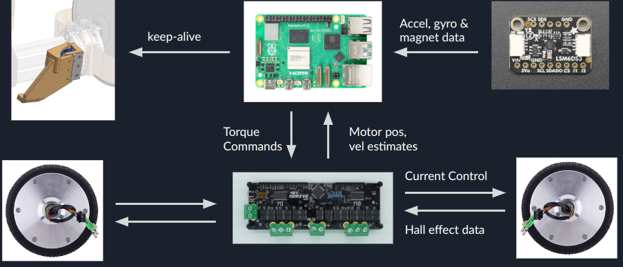
The overall control architecture is shown below:
LQR Controller
The LQR controller works by linearizing the system dynamics around a nominal operating point and then designing a controller that stabilizes the linearized system.
The LQR controller minimizes a cost function that penalizes deviations from the desired state and control inputs, and maximizes the performance of the system.
Benefits of LQR:
- Linear controller (runs quickly, very simple)
- Allows for simultaneous control of:
- position, velocity, pitch, pitch rate, yaw, yaw rate
- Perfect for path planning!
- Uses explicit robot model (very little tuning required!)
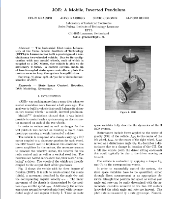
The paper we used to model the LQR is here.
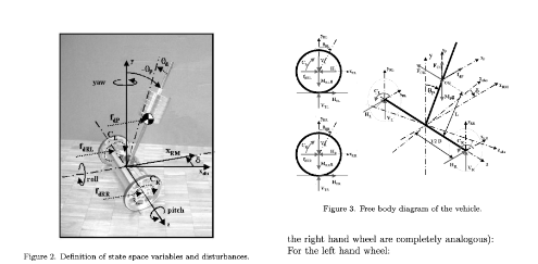
The test parameters we found are the following measured from the CAD and in real life:
- J_RL = 0.001 kg*m^2
- M_RL = 1.516 kg (left wheel)
- J_RR = 0.001 kg*m^2
- M_RR = 1.516 kg (right wheel)
- J_P0 = 1.858 kg*m^2
- J_Pd = 1.052 kg*m^2
- M_P = 6.278 kg
- R = 84.6mm
- D = 567mm
- L = 203mm
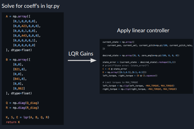
A snapshot of the LQR controller code is shown below. We use the control library in Python to handle the calculation of the LQR gains.